


STOKE ST MARY AND DISTRICT HISTORY GROUP
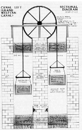
With no working prototypes, Green set about building seven lifts. The principle was simple. Two caissons were suspended from three carrying wheels of 16 feet (5 m) diameter, by wrought iron chains. The caisson at the bottom was jacked against the front wall of the lift to seal it, and a door or gate was opened to allow the boat to float in. The caisson at the top was jacked against the back wall in a similar manner. When both boats were in, the doors on the caissons and lift were closed, and the jacks released. Because a boat displaces its own weight in water, the system should be balanced, and a small amount of energy is required to start the boats moving. When the top caisson reaches the bottom, the jacks are applied, the doors are opened, and the boats can continue.
In order to maintain the balance, a second chain was fixed to the bottom of the caisson, so that the total length of chain on each side of the lift remained the same. As a caisson descended, the chain coiled up at the bottom of the lift. The small amount of energy was created by ensuring that the ascending caisson was a little too low by the time the descending one reached the bottom. Thus it would hold a greater depth of water by the time it was ready to descend again. In practice, about 2 inches (5 cm) of water, weighing about a ton, was found to be sufficient.
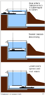
The system depended on the submerged, sealed box (the "caisson", from the French for "large chest") being heavily ballasted to achieve neutral buoyancy, so it was never possible in ordinary operation to lift it to water level to allow a descending boat to float in. Instead, a masonry chamber ("cistern") was built with walls higher than the water level in the top pound and itself filled completely with water, so that even at its upper position the box remained below the surface.[8] A vertically sliding door sealed the caisson from the top pound and kept the water in.
The mechanism was operated from the top level. For a descent, the box was first wound into its upper position using a double rack-
At the lower position the process was reversed. Here the water pressure was strong enough to press the box tightly into position against the exit opening. Another rack and pinion (again operated from above) lifted the outer gate, the levels were equalised again, the inner door on the box was swung open and the boat floated out. Apart from the inevitable leakage, no water had been used in the process.
No 1: February 1798: cracks
No 2: June 1798: success
No 3: April 1799: success
No 4: April 1799: success, in the presence of the Prince Regent
No 5: April 1799: success, transport of 60 passengers
No 6: May 1799: box jammed by a projecting stone
Construction of the first Caisson Lock (the uppermost of the flight) was completed and some work was begun on the site for the second one. During preliminary trials, several difficulties were found in the operation of the mechanism, which was inherently unstable due to the quantity of water inside the 'submarine' box. Unless the box was maintained absolutely level by a parallel-
The intended operating procedure for the Caisson Locks not known, but it can be deduced from available knowledge. There was no obvious requirement for the boatman to ride inside the caisson with his boat -
It was extremely dangerous if anything went wrong
He was needed to take the horse to the lower level while the caisson operator lowered the boat
It was easier to load and unload the boat from a position outside the caisson
To keep the box transversely stable, a system of rollers running against the sides of the chamber (probably bearing on iron plates) was used. This system eventually became distorted, probably by geological movements of the hillside and swelling of the surrounding soil when water leaking through the chamber masonry saturated it.
May 1799. The seriousness of the distortion was revealed when the S.C.C. Committee decided to risk a ride in the lift -
At this point, the Committee lost all confidence in the Caisson Lock system and decided to revert to the original plan of a flight of 22 conventional locks.
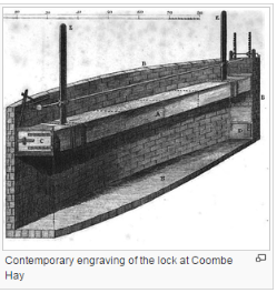
SOMERSET COAL CANAL
SEALED CAISSON LIFT
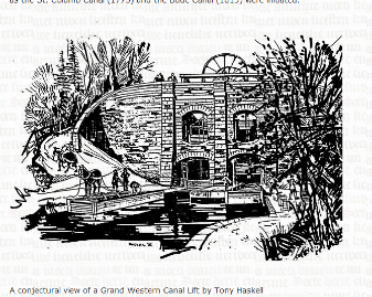
GRAND WESTERN BOAT LIFTS
Problems
The difficulty was that Anderson [whose idea it was] had suggested that the water in the caisson chambers should be at a lower level than that in the canal. This had not been implemented, and so the lower caisson would not sink deep enough for either boat to be floated out. Attempts to fit gates and to let the water in the chamber drain to waste had proved ineffective. Ultimately, lock chambers were built at the foot of the each lift. These were filled with water from the upper level, so that the boat could float out, and it then descended the final 3 feet (0.9 m) as it would in a conventional lock. Only the lift at Greenham used Anderson's principle, and included a proper drain to lower the level in the chambers.

